Hunan GCE Technology Co.,Ltd
jeffreyth@hngce.com
86-731-86187065

Product Details
Place of Origin: China
Brand Name: GCE
Certification: CE UL
Model Number: RBMS07S2-0-500A-750(512V)
Payment & Shipping Terms
Minimum Order Quantity: 2
Price: Negotiable
Packaging Details: Corrugated Carton, bundles, pallets, wooden box
Delivery Time: 8-15 working days
Payment Terms: L/C, T/T
Supply Ability: 1000+ pcs+per a week
|
Application:
|
Solar System, E-forklifts, Power Wall, Golf Carts, Home ESS,solar Energy Storage System,ups,bess
|
Communication:
|
RS485/CAN/LAN
|
Insulation Detection:
|
Optional
|
Module Strings:
|
16S*10
|
Dry Contact:
|
Yes
|
Battery Type:
|
LFP NMC LTO
|
Voltage:
|
512V
|
Current:
|
400A 500A
|
Color:
|
Black And Silver
|
Warranty:
|
3 Years
|
Product Name:
|
Batttery Management Sytem
|
|
Application:
|
Solar System, E-forklifts, Power Wall, Golf Carts, Home ESS,solar Energy Storage System,ups,bess
|
|
Communication:
|
RS485/CAN/LAN
|
|
Insulation Detection:
|
Optional
|
|
Module Strings:
|
16S*10
|
|
Dry Contact:
|
Yes
|
|
Battery Type:
|
LFP NMC LTO
|
|
Voltage:
|
512V
|
|
Current:
|
400A 500A
|
|
Color:
|
Black And Silver
|
|
Warranty:
|
3 Years
|
|
Product Name:
|
Batttery Management Sytem
|
#Product System Overview
![]()
#Product Feature
| 1 | Advanced Battery Management System --- The highly integrated battery management system enables seamless monitoring. |
| 2 | perfect self-test and operational status detection, with HMI display, system operation information at a glance. |
| 3 | perfect and reliable system control and protection strategies to fully protect the battery safety, extend the life of the battery escort. |
| 4 |
Modular design, configurable and expandable---multiple energy storage units can be
flexibly combined to expand into a larger energy storage system, which can support up to 256 cells (400 cells for lead-carbon batteries) in series.
|
| 5 |
Rich communication interfaces---multi-channel RS485, CAN, Ethernet, dry contact input
and output and other interfaces, support communication with most PCS and monitoring servers on the market.
|
| 6 |
The communication interface protocol is flexible---the factory comes with the company's
communication protocol, and can also adapt to the PCS of different manufacturers according to customer needs.
|
| 7 |
The capacity is big---the built-in large-capacity storage chip can store a large amount of key
operating data, and an SD card can be added to store the historical data of the battery cells
|
| 8 |
Automatic circulation control and automatic parallel/offline control can easily realize
parallel connection of battery packs.
|
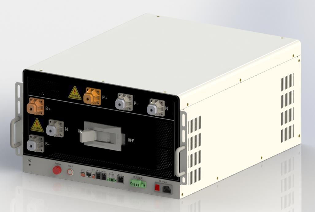
![]()
| No. | Name | Description | Precautions |
| 1 | B+ B- N | Power port connected to battery side total positive, total negative, and neutral |
Recommend to connecting bolt M10*16, torque 12-20N m |
| 2 | P+ P- N | Power port for connection to charging equipment (UPS) or DC bus |
Recommended connecting bolt M10*16, torque 12-20N m |
| 3 | AC Input | The municipal power supply input port must be taken from the UPS/Inverter output side | 85~264VAC 1A max |
| 4 | ON OFF | ON: The circuit breaker is ON. OFF: The circuit breaker is disconnected |
When the handle of the circuit breaker is in the trip state in the middle position, it needs to be turned OFF before it can be closed again. |
| 5 | D1 D1 D2 D2 | Two dry contact output reserved | Not yet open for use |
| 6 | Start | DC start button: start the RBMS system bytaking power from the battery side | The system is connected to the battery, after the circuit breaker is ON, press and wait for the light to turn on, indicating that the system is turned on |
| 7 | System | System status indicator | System normal: Green Alarm: yellow light Self test failure and protection status: red light
Charging: green light flashes Discharge: red light flashing Self checking: red and green flashing alternately Pre-charging: yellow flashing |
| 8 | 1 2 4 8 | ID allocation: When multiple RBMS are used in parallel, the ID are allocated by setting the DIP switch. Must start at 1 |
There are 4 DIP switches in total, supporting up to 15 RBMS in parallel 1 ON: ID+1 2 ON: ID+2 3 ON: ID+4 4 ON: ID+8 |
| 9 | TCP/IP | The RBMS host computer system software can be connected to the PC through the network cable | Network cable standard CAT5 or above, crossover cable or straight cable can be used, the line sequence can be according to the standard TIA-586A or TIA-568B |
| 10 | T-CAN T-485 |
Terminal matching resistance setting during can and 485 communication Setting Description: (120R), on is valid |
In parallel application, only the last one needs to be set. In stand-alone application, it can be used flexibly according to site conditions (interference, communication distance, etc.). |
| 11 | COM-IN COM-OUT |
RBMS external communication port: When multiple RBMS in parallel: Communication with SBMS When RBMS Stand-alone: communicate with UPS/PCS external devices |
The shielded twisted-pair cable harness must be used randomly. The cable sequence is defined in the cable harness label |
| 12 | GND HMI-B HMI-A 24V |
1.For external display connection 2.For powering SBMS |
Please connect the display screen according to the silk screen sequence |
| 13 | BMU-OUT | Communication interface with BMU | Cascaded communication between BMU |
| 14 | RBMS chassis ground | Must be grounded, and the grounding resistance is less than 1Ω |