Hunan GCE Technology Co.,Ltd
jeffreyth@hngce.com
86-731-86187065

Product Details
Place of Origin: China
Brand Name: GCE
Certification: CE
Model Number: 2U
Payment & Shipping Terms
Minimum Order Quantity: 2
Price: negotiate with:wenglin@hngce.com, WhatsAPP me: +86-15570747076
Packaging Details: Corrugated Carton, bundles, pallets, wooden box
Delivery Time: 20 work days
Payment Terms: T/T, L/C
Supply Ability: 2000 Sets per Month
|
Strings:
|
64S
|
Battery Type:
|
LFP/NMC/LTO
|
Max. Voltage:
|
350V, 500V(according To The Rated Voltage)
|
Max. Current:
|
50A
|
Voltage Range:
|
0V-96V
|
Current Sampling Accuracy:
|
1%FSR
|
Insulation Withstand Voltage:
|
2800VDC <1mA 1min
|
Size(W*H*D)mm:
|
2U (440*88*500)
|
Application:
|
BESS UPS Solar Energy Storage Systems
|
|
Strings:
|
64S
|
|
Battery Type:
|
LFP/NMC/LTO
|
|
Max. Voltage:
|
350V, 500V(according To The Rated Voltage)
|
|
Max. Current:
|
50A
|
|
Voltage Range:
|
0V-96V
|
|
Current Sampling Accuracy:
|
1%FSR
|
|
Insulation Withstand Voltage:
|
2800VDC <1mA 1min
|
|
Size(W*H*D)mm:
|
2U (440*88*500)
|
|
Application:
|
BESS UPS Solar Energy Storage Systems
|
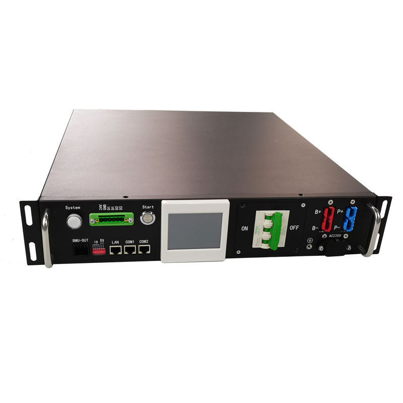
GCE RS485 CAN Protocol ESS BMS 204.8V50A 64S High Voltage 2U BMS
Product Features:
※ Advanced battery management system---The highly integrated battery management system can realize seamless monitoring.
※ Perfect self-checking and running status checking function, with HMI display screen, system running information is clear at a glance.
※ Complete and reliable system control and protection strategies, comprehensively guarantee battery safety and escort to extend the life of battery packs.
※ Modular design, configurable and expandable---multiple energy storage units can be flexibly combined and expanded into a larger energy storage system.
※ Abundant communication interfaces---multiple RS485, CAN, Ethernet, dry contact input and output interfaces, supporting communication with most PCS and monitoring servers on the market.
※ The communication interface protocol is flexible---the factory comes with the company's communication protocol, and it can also be adapted to the PCS of different manufacturers according to customer needs.
※ The built-in large-capacity memory chip can store a large amount of key operating data, and an SD card can be added to realize battery historical data storage
※ Automatic circulation control and automatic parallel/offline control can easily realize the parallel connection of battery packs.
![]()
Application:
◎ Photovoltaic power station energy storage
◎ Island off-grid energy storage
◎ ESS
◎ Micro-grid
◎ UPS power supply
◎ Power System 220V DC power supply
![]()
Product Specifications:
![]()
|
Basic Parameters |
|
| Max. current | 50A |
|
Max. voltage |
350V, 500V(according to the rated voltage) |
|
Power consumption |
≤15W |
|
Current sampling accuracy |
1%FSR |
|
Insulation withstand voltage |
2800VDC <1mA 1min |
|
Protection level |
IP20 |
|
Size(W*H*D) |
482*89*500(mm) |
|
New Weight |
~10Kg |
|
Communication Interface |
|
|
Communication port with BMU |
CAN |
|
Communication port with UPS |
RS485/CAN |
|
Communication port with SBMS |
RS485/CAN |
|
Communication with monitoring software |
Ethernet |
|
Basic Function |
|
|
Battery charge & discharge management |
Available |
|
Battery temperature management |
Available |
|
IAP Upgrade |
Available |
|
System protection parameter setting |
Available |
|
Short circuit protection |
Available(6KA 20ms) |
|
Pre-charge function |
Available |
|
Parallel circulation control |
Available |
|
Event record |
Available(5000) |
|
DC start |
Available(Battery powered, Mains supply is only for the signal to start on and off the BMS) |
|
Optional function |
|
|
Insulation detection |
No |
|
HMI display |
3.5 inches(Embedded in the chassis) |
|
Stand-alone or parallel function |
Set up before leaving the factory |
|
Dry contact |
Maximum 2 dry contact outputs |
|
Others |
|
|
Color |
RAL9005 black sand grain |
|
Installation method |
Suitable for standard 19-inch rack installation |
|
Incoming and outgoing wire method |
Front side in and front side out. |
|
Operating ambient temperature |
-20℃~60℃ |
|
Operating ambient humidity |
5%~75%RH |
|
Comply with National standards |
GB/T 16935.1 GB/T 17626.2 GB/T 17626.5 |
|
Certification |
Comply with CE certification standards |
RBMS Accessories List:
|
Name |
Specifications |
QTY |
Image |
|
Power Terminal |
GPS50AFP Blue |
1 |
|
|
Power Termina |
GPS50AFP Red |
1 | |
|
Power terminal connector |
S1339G2 |
4 | |
|
AC socket(writeable) |
250V 10A |
1 | |
|
Dry contact terminal |
5.08-6Pin |
1 | |
|
Terminating resistor |
120R |
1 |
Precautions For Use:
1)There is a high voltage inside the energy storage system. It is strictly forbidden to open the case for disassembly,
assembly and maintenance without the company or its authorized technicians, otherwise the electric shock will be released and the warranty rights will be lost.
2)It is strictly prohibited for any wire or connector in the BMS to overlap the positive and negative poles of the battery,
otherwise there may be a danger of short circuits and damage to the circuit board.
3)it is strictly prohibited to be close to the water source or fire source to avoid the fire of the battery due to a short circuit or overheating.
4)after the secondary protection is triggered, the circuit breaker is controlled by BMS. After disconnection, the system must be powered off to eliminate the fault,
and can be powered on and started again after an interval of at least 1 minute, otherwise, it may cause damage to the shunt coil of the circuit breaker because it is too late to emit heat.
5)If you need to cold start the UPS/PCS from the battery, you must first close the battery switch on the UPS/PCS side before starting the battery.
If you start the battery first, and then close the battery switch on the UPS/PCS side, since the DC side of the UPS/PCS side generally has a large capacitance,
the instantaneous capacitance is equivalent to a short circuit. At this time, the current charged by the battery to the capacitor will be much higher than that of the RBMS machine.
The rated value of the contactor is very easy to cause ablation and adhesion of the contactor's contact.
The contact resistance of the contactor's contact increases and heats up or the contact cannot be disconnected, which triggers the secondary protection
Safety Precautions:
1)The tools used by installation and commissioning personnel must have insulation protection.
2)During installation, debugging and maintenance, you must wear insulated rubber gloves, goggles, and insulated rubber boots as appropriate to avoid safety accidents as much as possible.
3)If the metal of the wire ends during the installation, debugging and maintenance process falls into the battery room, be sure to use an insulated tool to take it out, and do not leave the sundries.
4)When maintenance is required, the main circuit breaker of the RBMS must be disconnected, and the connection between the battery pack and the PCS DC bus must be cut off.
5)According to different project requirements, the parameters such as the charge and discharge current and charge and discharge voltage of the battery management system have been set during the initial installation and commissioning.
The parameters must not be changed without authorization, otherwise, the battery life may be shortened, and the battery may be affected more seriously. Cause serious harm and cause safety accidents.
6)In case of fire around the energy storage cabinet, please use a dry powder fire extinguisher or fire sand to extinguish the fire. Using liquid to extinguish the fire may cause electric shock.
7)If the system is not used for a long time, be sure to disconnect the main circuit breaker of the battery cabinet.
8)Try to avoid long-term use in the following working environment:
◎Places that exceed the temperature or humidity range specified in the specification
◎Places subject to strong vibration or susceptible to impact
◎Places exposed to direct sunlight or close to heat sources
◎Places with dust, strong corrosive substances, flammable and explosive materials, and high salt spray